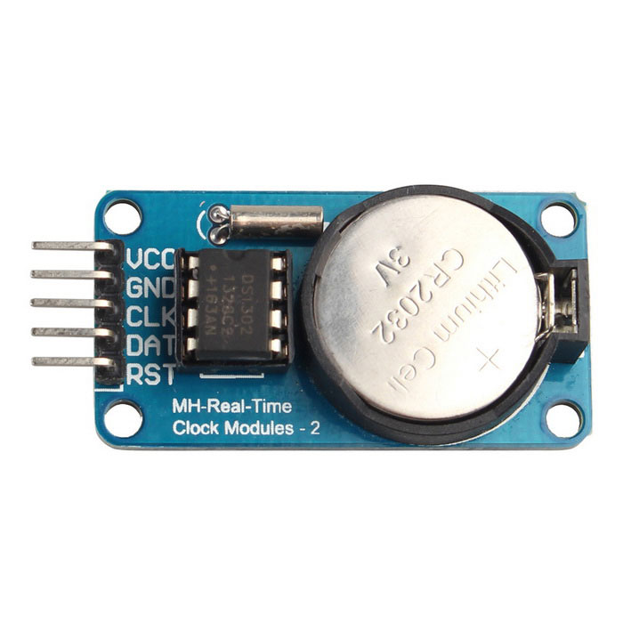
RTC INTERFACING WITH ARDUINO
A Real Time Clock module is basically a time tracking device which gives the current time and date. In this article you will learn how to interface real time clock DS1307 with Arduino (by using ATmega328p) using 16×2 LCD module for display.
Synopsis

A Real Time Clock module is basically a time tracking device which gives the current time and date. RTC module that comes with DS3231 IC have the provision to set alarms. Here we are using an RTC module with clock chip DS1307 based on I2C protocol (Two Wire Protocol). The module provides details such us second, minute, hour, day of week, day of month, month and year including correction for leap year.

In this article you will learn how to interface real time clock DS1307 with Arduino (by using ATmega328p) using 16×2 LCD module for display.

Description

Real time clock is used to keep record off time and to display time. It is used in many digital electronics devices like computers, electronics watches, date loggers and situation where you need to keep track of time. One of the great benefits of real time clock is that it also keep record of time even if power supply is not available. Some electronic devices like real time clock work without use of power supply because it have small power cell of about 3-5 volt inside which can work for years. Because real time clock consume minimum amount of power.

DS1307 can operate either in 12 Hour or in 24 Hour format. Current consumption of this module is nano ampere range . Even a 3V battery can power it for 10 years maintaining an accurate clock and without any external power. DS1307 has a memory area of 64 bytes of which the first 8 bytes are reserved as RTC register area and the remaining 56 bytes are allotted as general purpose RAM. The details about current date and time is stored in its register area as Binary Coded Decimals. The module communicates with the microcontroller using a serial communication protocol called I2C. The I2C bus physically consists of 2 active wires. The wires, called SDA and SCL, are both bi-directional. SDA is the Serial Data line, and SCL is the Serial CLock line. Every device connected to the bus has its own unique device address, no matter whether it is an MCU or RTC module. Each of these chips can act as a receiver or transmitter, depending on the functionality.

DS1307 will act as slave in the communication network and controller can only access the slave by initiating a start condition along with a device address. There after we need to send the register number in order to access the value inside. The interface to the Arduino is simple I2C with SDA and SCL pins are connected to the corresponding I2C pins of arduino. At the software side we are using an arduino library named “Wire” for I2C communication. This library allows you to communicate with I2C / TWI devices.

The DS 1307 is specifically designed for timekeeping, The time is fairly accurate with an error (time drift) of about 1 minute per month. If u want to eliminate this u can go for the DS3234 which has a time drift of only 1 minute per year. For our particular application we can settle for the DS1307 itself.

The DS 1307 communicates with the arduino using I²C protocol. Simply put the chip sends data in decimal form such that each decimal form is 4 bits of binary data also known as Binary Coded Decimal System. It is a 8 bit IC. It is used to make real time clock using some other electronic components. Pin configuration of DS1307 is given below:


Important Pins

Pin 1 & 2 are used for crystal oscillator . Crystal oscillator value usually used with DS1307 is 32.768k Hz.

Pin 3 is used for back up battery. Its value should be between 3-5 volt. voltage more than 5 volt may burn DS1307 permanently. Back battery is used to keep track of time in case of power failure to DS1307. After getting power DS1307 shows correct time due to back up battery.

Pin 4 is ground pin of power supply.

Pin 5 & 6 are used to communicate with other devices with the help of I2C communication protocol. Pin 5 (SDA) is serial data pin and pin 6 (SCL) is serial clock.

You need external components to connect with DS1307 to use it as a real time clock. Circuit diagram with necessary components is given below:


In above circuit diagram there is no connection for power supply and ground at pin number four and eight. Don’t forget to to provide power supply of 5 volt to this circuit while making this circuit.

Applications

>> Once you are done with this Instructable you will be able to make your own Digital Clock.

>> You can build on the idea and make an Alarm Clock.

>> This Module is the timekeeper for many projects like The Propeller Clock, The Nixie Clock, etc.

Proteus design for RTC interfacing with Arduino


Orcad design for RTC interfacing with Arduino


RTC interfacing with Arduino

/*  Name     : main.c
 *  Purpose  : Source code for RTC Interfacing with Arduino.
 *  Author   : Gemicates
 *  Date     : 22-01-2018
 *  Website  : www.gemicates.org
 *  Revision : None
 */
#include <Wire.h>
#define DS1307_I2C_ADDRESS 0x68
#include <LiquidCrystal.h>                                   // we need this library for the LCD commands
LiquidCrystal lcd(4, 5, 6, 7, 8, 9, 10, 11, 12, 13);
                                                             // Convert normal decimal numbers to binary coded decimal
byte decToBcd(byte val)
{
return ( (val/10*16) + (val%10) );
}
                                                             // Convert binary coded decimal to normal decimal numbers
byte bcdToDec(byte val)
{
return ( (val/16*10) + (val%16) );
}
                                                             // 1) Sets the date and time on the ds1307
                                                             // 2) Starts the clock
                                                             // 3) Sets hour mode to 24 hour clock
                                                             // Assumes you're passing in valid numbers
void setDateDs1307(byte second,                              // 0-59
byte minute,                                                 // 0-59
byte hour,                                                   // 1-23
byte dayOfWeek,                                              // 1-7
byte dayOfMonth,                                             // 1-28/29/30/31
byte month, // 1-12
byte year) // 0-99
{
Wire.beginTransmission(DS1307_I2C_ADDRESS);
Wire.write(0);
Wire.write(decToBcd(second));                               // 0 to bit 7 starts the clock
Wire.write(decToBcd(minute));
Wire.write(decToBcd(hour));
Wire.write(decToBcd(dayOfWeek));
Wire.write(decToBcd(dayOfMonth));
Wire.write(decToBcd(month));
Wire.write(decToBcd(year));
Wire.write(0x10);                                           // sends 0x10 (hex) 00010000 (binary) to control register - turns on square wave
Wire.endTransmission();
}
                                                            // Gets the date and time from the ds1307
void getDateDs1307(byte *second,
byte *minute,
byte *hour,
byte *dayOfWeek,
byte *dayOfMonth,
byte *month,
byte *year)
{
                                                            // Reset the register pointer
Wire.beginTransmission(DS1307_I2C_ADDRESS);
Wire.write(0);
Wire.endTransmission();
Wire.requestFrom(DS1307_I2C_ADDRESS, 7);
                                                            // A few of these need masks because certain bits are control bits
*second = bcdToDec(Wire.read() & 0x7f);
*minute = bcdToDec(Wire.read());
*hour = bcdToDec(Wire.read() & 0x3f);                       // Need to change this if 12 hour am/pm
*dayOfWeek = bcdToDec(Wire.read());
*dayOfMonth = bcdToDec(Wire.read());
*month = bcdToDec(Wire.read());
*year = bcdToDec(Wire.read());
}
void setup()
{
byte second, minute, hour, dayOfWeek, dayOfMonth, month, year;
Wire.begin();
Serial.begin(9600);
                                                            // Change these values to what you want to set your clock to.
                                                            // You probably only want to set your clock once and then remove
                                                            // the setDateDs1307 call.
second = 0;
minute = 46;
hour = 2;
dayOfWeek = 4;
dayOfMonth = 7;
month = 2;
year = 13;
                                                            // setDateDs1307(second, minute, hour, dayOfWeek, dayOfMonth, month, year);
lcd.begin(16, 2);                                           // tells Arduino the LCD dimensions
lcd.setCursor(0,0);
lcd.print("GEMICATES LABS");                                // print text and move cursor to start of next line
lcd.setCursor(0,1);
lcd.print("RealTimeClock");
delay(100);
lcd.clear();                                                // clear LCD screen
}
void loop()
{
byte second, minute, hour, dayOfWeek, dayOfMonth, month, year;
getDateDs1307(&second, &minute, &hour, &dayOfWeek, &dayOfMonth, &month, &year);
lcd.clear();                                                // clear LCD screen
lcd.setCursor(0,0);
lcd.print(" ");
lcd.print(hour, DEC);
lcd.print(":");
if (minute<10)
{
lcd.print("0");
}
lcd.print(minute, DEC);
lcd.print(":");
if (second<10)
{
lcd.print("0");
}
lcd.print(second, DEC);
lcd.setCursor(0,1);
lcd.print(" ");
switch(dayOfWeek){
case 1:
lcd.print("Sun");
break;
case 2:
lcd.print("Mon");
break;
case 3:
lcd.print("Tue");
break;
case 4:
lcd.print("Wed");
break;
case 5:
lcd.print("Thu");
break;
case 6:
lcd.print("Fri");
break;
case 7:
lcd.print("Sat");
break;
}
lcd.print(" ");
lcd.print(dayOfMonth, DEC);
lcd.print("/");
lcd.print(month, DEC);
lcd.print("/20");
lcd.print(year, DEC);
delay(60);
}

Error message here!

Show Error message here!


Forgot your password?

Error message here!

Send OTP

Error message here!

Show Error message here!


Lost your password? Please enter your email address. You will receive a password you Need.

Send Error message here!


Back to log-in

Close